In hazardous industries such as oil & gas, petrochemicals, mining, and pharmaceuticals, electrical equipment must operate safely in explosive atmospheres. One of the most widely used protection methods is Flameproof Enclosures (Ex d). The core safety principle of Ex d is to contain an internal explosion and prevent flame or hot gases from igniting the surrounding atmosphere.
At the heart of this protection strategy lies flameproof joint gap tolerances, along with flame path machining accuracy, strict surface roughness requirements, and mitigation of pressure-piling effects. Understanding these technical parameters is crucial for engineers, manufacturers, and safety professionals designing or maintaining Ex d equipment.
What Are Flameproof Joint Gap Tolerances?
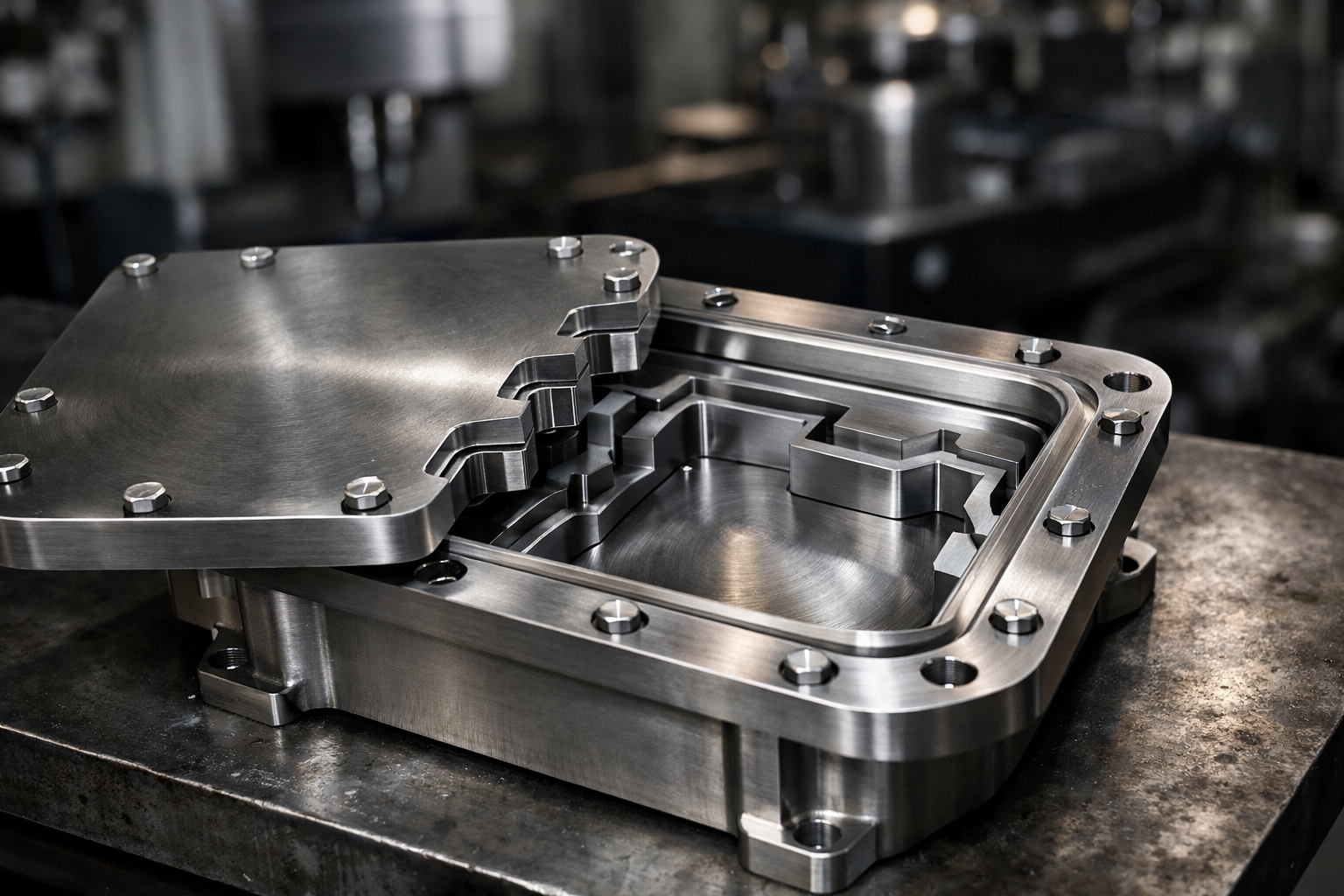
A flameproof joint is the interface between two parts of an enclosure (e.g., cover and body) through which flames could potentially propagate if an internal explosion occurs. Flameproof joint gap tolerance refers to the maximum permissible spacing between mating surfaces of the enclosure such that hot combustion gases lose heat and are cooled before emerging outside, thus preventing ignition.
In Ex d design, joints are engineered with gas-tight and flame-quenching characteristics. If the gap is too wide or improperly machined, the flame impinges on uncooled surfaces, significantly increasing the risk of external ignition.
SEO Keywords: flameproof joint gap tolerance, Ex d enclosure design, flame path machining accuracy, surface roughness limits, pressure piling phenomenon.
Why Flame Path Machining Accuracy Matters
The flame path is the actual path that hot combustion gases would follow to escape an enclosure. This includes machined surfaces like:
To maximize safety, these surfaces must be precisely machined to exacting tolerances. Why?
1. Controlled Flame Spread
Accurate machining ensures that the flame path geometry supports flame quenching—cooling of the flame as it travels through designed clearances. Inaccurate machining produces uneven gaps, hotspots, and localized paths that allow flames to penetrate.
2. Improved Thermal Dissipation
Tight, even surfaces increase contact area and thermal conduction to the body of the enclosure. This helps dissipate heat from hot gases.
3. Compliance With Standards
Standards such as IEC 60079-1 mandate specific machining tolerances. For example, mill finishes and closely controlled joint gaps directly affect compliance verification and approvals.
Real-World Relevance: Major industrial manufacturers such as Schneider Electric, Siemens, and ABB invest heavily in precision CNC machining and inspection technologies to meet these tolerance requirements and pass third-party certification testing.
Surface Roughness Limits: Smooth Is Safe
Surface roughness refers to the microscopic texture of a machined surface. It is measured in micrometers (µm), and for Ex d flame paths, surfaces must be smooth enough to limit turbulent hot gas pockets.
Why Surface Roughness Matters
Industry Practice
Many flameproof designs require a surface roughness (Ra) of ≤ 3.2 µm on flame path ribs and joint surfaces. Some critical applications (e.g., subsea or high-pressure refining) demand even tighter finishes of ≤ 1.6 µm.
Big Player Example: Emerson Electric (including Cooper Crouse-Hinds) utilizes multi-axis precision grinding and lapping at controlled Ra levels to ensure surface consistency and certification compliance.
The Pressure-Piling Phenomenon: A Hidden Hazard
Pressure-piling refers to the super-additive pressure rise inside inter-connected volumes during an explosion when multiple chambers are linked by small passageways. In the context of Ex d enclosures, pressure piling becomes critical when:
How It Works
If an explosion occurs in one chamber, flame and pressure travel through the interconnecting path. The confined geometry and timing delays can cause overlapping pressure waves, producing peak pressures far above anticipated values. This stresses the enclosure and can compromise the effectiveness of flame paths.
Mitigating Pressure Piling
Example in Practice: Eaton’s explosion-proof enclosures are designed with internal partitioning and enhanced flame paths to mitigate pressure piling during certification tests.
Flameproof Joint Gap Tolerance: Numbers That Matter
You may have seen figures like 0.15 mm, 0.25 mm, 0.4 mm in standards texts. These vary based on:
The general engineering principle is:
Smaller gaps equate to stronger flame quenching and reduced flame propagation outside the enclosure.
Below is a comparison of typical design parameters used in Ex d applications:
Flameproof Joint Parameters: Comparison Table
|
Parameter |
Typical Range |
Influence on Safety |
|
Flameproof Gap Tolerance |
0.15 mm – 0.4 mm |
Smaller = better gas cooling and quenching |
|
Surface Roughness (Ra) |
≤1.6 µm – ≤3.2 µm |
Smoother = less heat retention |
|
Flame Path Length |
5 mm – 12 mm (dependent on group) |
Longer = better cooling |
|
Material Flatness Deviation |
≤0.05 mm per 100 mm |
More flat = consistent gap control |
|
Bolt Torque Accuracy |
±5 % |
Ensures uniform joint closure |
These values are illustrative. Reference IEC 60079-1, EN 60079-1, and local jurisdiction codes for product certification and design validation.
Real-Life Examples: Who Uses Ex d Flameproof Tolerances?
1. Oil & Gas Platforms
Platforms such as Shell’s Gulf of Mexico facilities rely on Ex d cabinets for motor starters, lighting controls, and instrumentation. Here, the accuracy of flameproof joints directly affects safety in zones 1 & 2.
2. Chemical Processing Plants
Companies like Dow Chemical and BASF operate plants with volatile organic compounds. Flameproof components designed with tight gap tolerances are essential for risk mitigation.
3. Mining Electrification
Inside coal mines, methane risk mandates Ex d rated equipment. Manufacturers such as Gefa Elektrik and Pepperl+Fuchs produce flameproof junction boxes and sensors with surface finishes optimized for explosion safety.
4. Refineries
Major refiners like ExxonMobil deploy flameproof instrumentation and actuators that are certified to withstand internal explosions without propagation.
Best Practices for Flameproof Joint Manufacturing
To ensure reliable Ex d performance:
1. Use High-Precision CNC Machining
Five-axis CNC lathes and milling machines allow complex flame path geometries to meet tight tolerances.
2. Conduct 100 % Inspection
Coordinate measuring machines (CMMs) verify dimensional tolerances and surface roughness gauges confirm Ra values.
3. Apply Controlled Surface Treatments
Processes such as grinding, honing, and lapping improve joint surfaces.
4. Verify Bolt Torque and Assembly
Uniform torque prevents localized gaps that defeat flame path integrity.
5. Perform Sample Explosion Testing
Verify in real explosion chambers that the enclosure withstands internal deflagration without external ignition.
Common Misconceptions
Myth: Any metal enclosure can be made explosion-proof by thick walls.
Fact: Flameproof integrity depends on engineered joint design, machining precision, and gap control, not thickness alone.
Myth: Gaskets replace the need for precise machining.
Fact: Gaskets are sealing components but do not replace flame path machining tolerances—machined surfaces are the primary flame quenching system.
FAQs
1. What is the purpose of flameproof joint gap tolerance?
Answer: It limits the space between mating surfaces to ensure hot combustion gases cool before escaping, preventing ignition of surrounding explosive atmospheres.
2. Why is surface roughness critical in Ex d enclosures?
Answer: Smoother surfaces reduce micro-crevices that trap hot gases, improve thermal conduction, and increase the flame quenching effect.
3. How does pressure piling affect flameproof equipment?
Answer: Pressure piling can generate higher internal pressures when explosions propagate through interconnected volumes, challenging enclosure design and flame path efficacy.
4. Which standards govern flameproof joint tolerances?
Answer: Standards like IEC 60079-1, EN 60079-1, and equivalent national regulations specify gap tolerances, surface finishes, and test procedures.
5. Can field repairs compromise flange gap tolerances?
Answer: Yes. Improper repair, poor surface finishing, or incorrect bolt torque can alter gap tolerances and defeat flame quenching properties, necessitating recertification.