
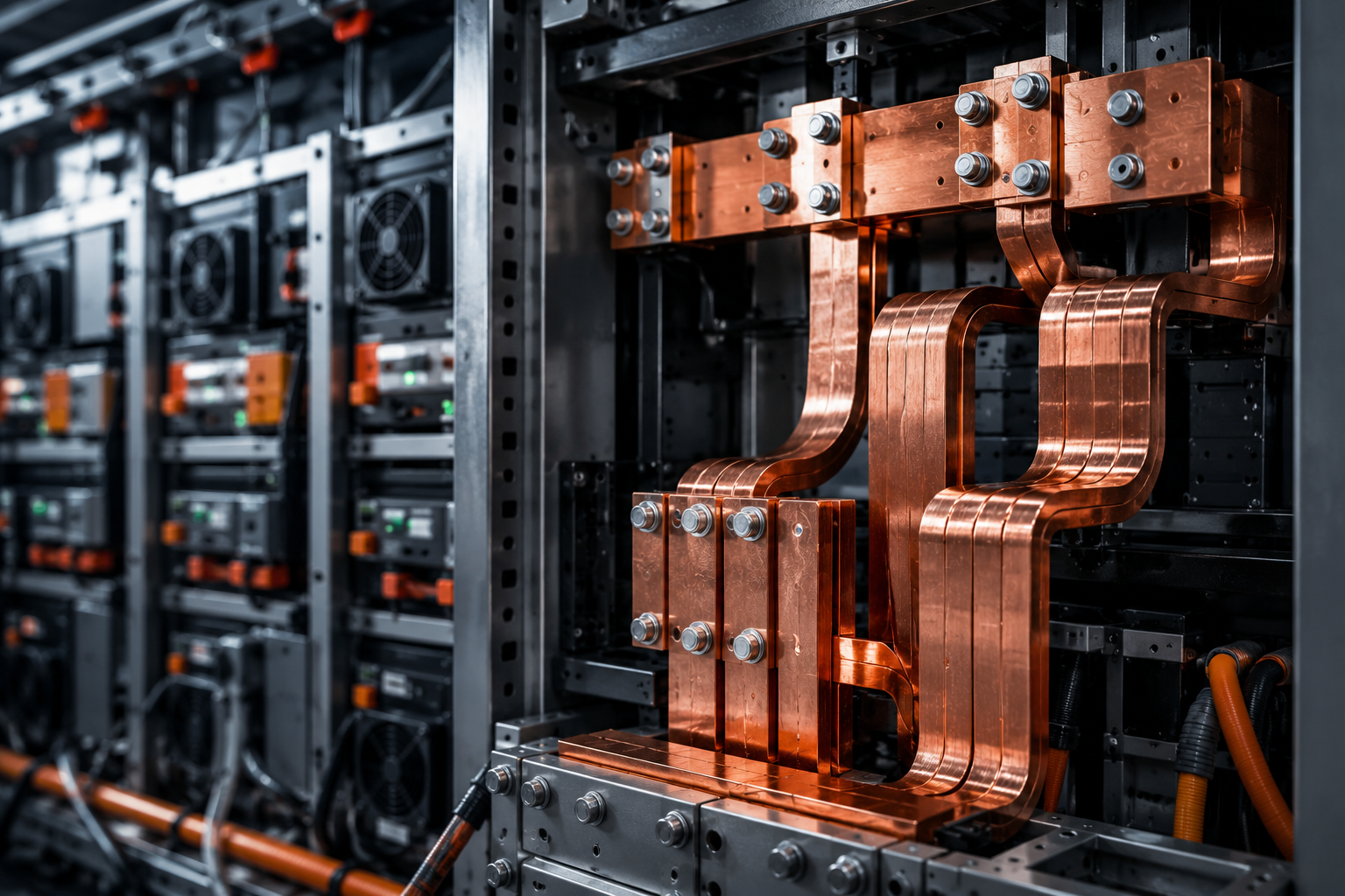
As Battery Energy Storage Systems (BESS) scale from kilowatt-level applications to multi-megawatt installations, the electrical infrastructure supporting the system becomes increasingly critical.
While batteries, Power Conversion Systems (PCS) and Energy Management Systems (EMS) often receive the most attention, busbars form an essential part of the BESS power path. They carry high levels of current between battery racks, PCS units, protection devices and power distribution equipment.
In high-power BESS applications, busbar design is not simply about selecting a conductor based on its current rating. It requires a detailed evaluation of current density, temperature rise, thermal expansion, electrical clearances, joint performance and short-circuit withstand capability.
A well-engineered BESS busbar system helps maintain efficient power flow during normal operation while providing the thermal and mechanical strength required to perform reliably under demanding operating and fault conditions.
As BESS capacity increases, system currents can become substantial, particularly in low-voltage, high-power configurations. The busbar system must safely manage these currents while operating within acceptable thermal and mechanical limits.
An ineffective busbar design can contribute to:
Excessive temperature rise
Higher electrical losses
Localized hotspots at joints
Reduced insulation life
Mechanical stress caused by thermal movement
Reduced electrical clearances
Damage during short-circuit events
Lower system reliability and availability
For this reason, busbar design must be integrated with the complete BESS electrical architecture rather than treated as an independent component.
Current density refers to the amount of electrical current flowing through a given cross-sectional area of the conductor.
Current Density = Current ÷ Busbar Cross-Sectional Area
At high current levels, an undersized busbar can create excessive electrical resistance and heat generation. This can increase conductor temperature, affect insulation performance and introduce additional thermal stress at joints and connected equipment.
However, busbar sizing is not based on current rating alone.
The actual current-carrying capability of a BESS busbar depends on several factors, including:
Conductor material, such as copper or aluminium
Busbar cross-sectional area
Busbar thickness and width
Installation orientation
Ambient temperature
Enclosure ventilation and cooling
Busbar spacing
Number of parallel conductors
Surface finish and joint design
Continuous, peak and overload current
BESS systems may operate across varying charge and discharge profiles. Therefore, the busbar should be designed around the complete operating duty rather than only the nominal current value.
The objective is not simply to carry more current. The objective is to maintain acceptable temperature rise, reduce unnecessary electrical losses and support reliable long-term operation.
Electrical losses within a busbar are influenced by conductor resistance and current. As current increases, heat generation can rise significantly.
This makes thermal performance a key part of high-power BESS busbar design.
Even when the main busbar is correctly sized, poorly designed or assembled joints can become localized thermal hotspots. Increased contact resistance may result from inadequate contact area, improper surface preparation, incorrect fastening hardware or insufficient tightening torque.
Over time, repeated charging and discharging cycles may further affect the thermal performance of these connections.
A reliable BESS busbar system should consider:
Maximum continuous charging current
Maximum continuous discharge current
Short-duration overload conditions
Expected ambient temperature
Heat generated by nearby electrical equipment
Enclosure airflow and cooling capability
Permissible temperature rise
Joint contact resistance
Thermal evaluation should not be limited to the main conductor. Busbar joints, terminations and equipment connections must also be assessed because these locations can become critical points in the electrical power path.
Busbars expand as their temperature increases and contract as they cool.
In a BESS, changing charge and discharge conditions can create regular temperature variations across the electrical system. Over time, repeated thermal cycling may introduce mechanical stress if conductor movement is not considered during the design stage.
A long and rigid busbar with insufficient allowance for expansion may transfer stress to:
Busbar supports
Bolted joints
Insulators
Equipment terminals
Connected cables and conductors
This may contribute to joint loosening, misalignment, increased contact resistance or mechanical damage.
Thermal expansion becomes particularly important in high-current BESS systems where conductor temperatures may vary significantly between different operating conditions.
To manage thermal movement, the busbar design may include:
Expansion arrangements
Flexible links or connectors
Optimized support locations
Controlled busbar lengths
Appropriate phase spacing
Adequate allowance for conductor movement
The objective is to allow controlled thermal expansion without compromising electrical clearances, mechanical stability or connection integrity.
A BESS busbar must be designed not only for normal operating current but also for the conditions created during an electrical fault.
During a short circuit, extremely high current may flow through the system for a short duration. These currents generate strong electromagnetic forces between conductors.
The resulting mechanical stress can cause busbars to:
Bend or deform
Move toward or away from adjacent conductors
Damage insulation supports
Reduce phase-to-phase clearances
Loosen or damage joints
Transfer excessive force to connected equipment
The severity of these forces depends on factors such as fault current, fault duration, conductor spacing, busbar geometry and support arrangement.
For high-power BESS systems, fault withstand capability must be evaluated as both an electrical and mechanical requirement.
A busbar may have sufficient thermal capacity but still experience mechanical failure if its supports, spacing or fastening arrangement are not designed for the expected fault level.
Key design considerations include:
Prospective short-circuit current
Fault duration
Peak withstand current
Busbar spacing
Support spacing
Busbar cross-section and orientation
Mechanical strength of busbar supports and insulators
Joint and fastening capability
The complete busbar assembly must remain stable during the fault event while maintaining the required electrical clearances.
A busbar system is only as reliable as its connections.
At high current levels, even a small increase in contact resistance can generate significant localized heating. Joint design must therefore consider contact area, surface condition, hardware selection and tightening torque.
Effective busbar joint engineering includes:
Properly prepared contact surfaces
Suitable plating or surface treatment where required
Correct bolt size and hardware selection
Specified tightening torque
Controlled and consistent contact pressure
Appropriate joint overlap
Reliable inspection and quality checks
For critical BESS applications, temperature monitoring and periodic thermal inspection can help identify developing issues before they affect system availability.
The busbar cannot be designed in isolation.
Its performance is influenced by the complete electrical and mechanical architecture of the Battery Energy Storage System, including:
Battery rack configuration
Battery voltage and current
BESS power rating
PCS configuration
DC and AC distribution arrangement
Protection coordination
Enclosure dimensions
Cooling and ventilation systems
Cable routing
Equipment terminal locations
Installation and maintenance requirements
For example, a busbar designed only around electrical current may not fit efficiently within the enclosure or may restrict airflow. Similarly, a mechanically robust arrangement may create unnecessary conductor length and additional electrical losses if the overall system layout is not optimized.
Effective BESS busbar design requires electrical, thermal and mechanical requirements to be evaluated together.
In high-power Battery Energy Storage Systems, busbars are more than conductive links. They are a critical part of the system’s electrical backbone.
The right busbar design helps:
Carry high current efficiently
Control temperature rise
Reduce electrical losses
Accommodate thermal expansion
Maintain reliable electrical connections
Withstand mechanical forces during faults
Support long-term BESS reliability and availability
As BESS capacities continue to grow, busbar engineering must move beyond basic ampere ratings and conductor sizing. The focus must be on the complete power path—from conductor selection and joint design to thermal performance, mechanical support and short-circuit capability.
At Brick & Byte, we engineer BESS electrical infrastructure by considering the complete system—not only individual components.
Our approach integrates high-current power distribution, busbar engineering, thermal performance, mechanical strength, protection requirements and manufacturing precision to support demanding BESS applications.
Whether the requirement involves a modular BESS, containerized energy storage system or large-scale grid-connected installation, the electrical infrastructure must be designed to support reliable power flow throughout the system lifecycle.
Looking to develop or scale a high-power BESS solution?
Connect with Brick & Byte to discuss your BESS electrical infrastructure requirements—from high-current busbar systems and power distribution to integrated electrical enclosures and application-specific manufacturing.
Contact our BESS team to explore an engineered solution for your application.
Busbar design affects current-carrying capability, temperature rise, electrical losses, fault performance and the overall reliability of the BESS electrical infrastructure.
Current density is the amount of current flowing through a specific cross-sectional area of the busbar. It helps determine conductor sizing and influences temperature rise and electrical performance.
Busbars expand and contract as their temperature changes. If thermal movement is not accommodated, it can create mechanical stress at joints, supports, terminals and connected equipment.
Fault withstand capability refers to the ability of a busbar system to tolerate the thermal and mechanical effects of a short-circuit current without damage or loss of required electrical clearances.
Reliability can be improved through appropriate conductor sizing, thermal design, optimized support spacing, robust joint engineering, controlled assembly practices and application-specific testing.


Why Internal Equipment Placement Makes or Breaks Reliability
Read More