A+B redundancy is often seen as the gold standard in data center reliability. Two independent power paths. Dual feeds. Separate UPS systems. On paper—it looks bulletproof.
But in reality? Many of these “redundant” systems quietly share hidden dependencies that can take down entire facilities in seconds.
Introduction: The Illusion of Safety in Redundant Power Design
Modern data centers are designed with one primary goal: zero downtime. To achieve this, most operators implement A+B power architecture, where two independent electrical paths feed critical loads.
This approach is aligned with global standards like those from the Uptime Institute and is commonly associated with Tier III and Tier IV facilities.
However, a growing number of real-world failures suggest a hard truth:
Redundancy on schematics does not always translate to redundancy in reality.
Hidden single points of failure (SPOFs) continue to exist—embedded in infrastructure layers that are often overlooked during design, execution, or expansion.
What is A+B Power Architecture? (And Why It’s Trusted)
In a typical A+B setup:
Two independent power sources (Utility A and Utility B or Generator A/B)
Dual UPS systems
Separate switchgear and distribution paths
IT equipment with dual power supplies
The expectation:
If Path A fails, Path B seamlessly takes over—without downtime.
This model is widely used by hyperscalers like Amazon Web Services, Google Cloud, and Microsoft Azure, as well as colocation giants like Equinix and Digital Realty.
But even these industry leaders have faced outages—proving that redundancy is only as strong as its weakest hidden link.
Where the Problem Lies: Hidden Single Points of Failure
Despite well-designed redundancy at a macro level, several micro-level overlaps create unintended vulnerabilities:
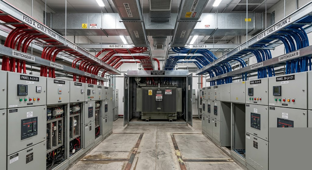
1. Shared Bus Duct Systems
Bus ducts are often used for compact, high-capacity power distribution. However:
A single bus duct corridor may carry both A and B feeds
Fire, insulation failure, or mechanical damage can affect both paths simultaneously
Reality Check:
In multiple colocation facilities, bus duct faults have led to cascading failures—because both “independent” feeds were physically co-located.
2. Common Upstream Transformers
Even when A+B exists downstream:
Both feeds may originate from the same transformer yard
Or worse, a single utility substation
This creates a primary dependency risk.
Industry Insight:
The Delta Air Lines data center outage 2016 was triggered by a power control failure that cascaded across systems, highlighting upstream vulnerabilities.
3. Cable Routing Overlaps
Cable separation is often assumed—but not always enforced:
A and B cables routed through the same trench, tray, or shaft
Fire, flooding, or human error can impact both simultaneously
Example:
A major outage in a European data center cluster (affecting cloud services) was linked to fire suppression activation in a shared cable zone—impacting redundant feeds.
4. Shared Switchgear Rooms
Even with separate panels:
Housing them in the same electrical room introduces environmental risk
Fire, arc flash, or HVAC failure can compromise both systems
5. Human Intervention Risk
Ironically, redundancy often fails during:
Maintenance
Upgrades
Emergency switching
Case in Point:
The British Airways IT outage 2017 was caused by a power supply issue during maintenance, leading to a massive global disruption.
Comparison: True Redundancy vs False Redundancy
| Parameter | True A+B Redundancy | False Sense of Redundancy |
| Power Source | Independent utilities or substations | Same upstream substation |
| Transformer | Physically and electrically isolated | Shared or adjacent transformer yard |
| Cable Routing | Separate physical routes | Shared trays / ducts |
| Bus Ducts | Completely segregated | Common bus duct systems |
| Switchgear | Separate rooms/zones | Same room with partitions |
| Maintenance Impact | One path fully operational | Both paths at risk |
| Failure Outcome | No downtime | Full or partial outage |
Real-World Incidents That Prove the Risk
1. Cloud Outages and Power Dependencies
Even hyperscalers like Amazon Web Services have experienced outages linked to power events in specific regions—demonstrating that redundancy must extend beyond IT layers into electrical infrastructure.
2. Colocation Failures
Facilities operated by global players like Equinix and Digital Realty have faced localized outages due to electrical faults—often tied to distribution-level dependencies rather than complete system failure.
3. Airline Industry Disruptions
The Delta Air Lines data center outage 2016 and British Airways IT outage 2017 collectively cost hundreds of millions—both rooted in power infrastructure weaknesses.
Why This Problem Is Increasing Today
1. High-Density Loads
Modern data centers (AI, HPC, hyperscale) demand:
Higher power density
Compact infrastructure
This leads to:
Shared pathways
Space optimization compromises
2. Retrofit Expansions
Many facilities are expanded over time:
Original separation gets diluted
New loads are integrated into existing infrastructure
3. Cost Optimization Pressures
True redundancy is expensive:
Separate substations
Duplicate routing
Independent infrastructure
To reduce CapEx, compromises are often made—introducing hidden SPOFs.
How to Design Truly Resilient A+B Systems
1. Enforce Physical Separation
Separate cable trays, shafts, and entry points
No shared pathways—even for short distances
2. Independent Upstream Sources
Dual substations (not just feeders)
Avoid single utility dependency where possible
3. Segregated Bus Duct Design
Dedicated bus ducts for A and B
Fire-rated barriers between them
4. Zonal Isolation
Separate electrical rooms
Fire compartmentalization
5. Maintenance-Proof Design
Ensure one path can handle full load independently
No cross-dependency during switching
6. Audit Beyond Drawings
Physical inspection is critical
Verify actual routing—not just design intent
The Role of Advanced Engineering & Manufacturing
This is where companies specializing in end-to-end electrical infrastructure—like switchboards, enclosures, and power systems—play a critical role.
Properly designed:
LV/MV panels (IEC 61439 compliant)
High IP-rated enclosures (IP55/IP66)
Robust busbar and cable management systems
…can significantly reduce hidden vulnerabilities.
The focus must shift from:
“Do we have redundancy?”
to
“Is our redundancy truly independent at every layer?”
Conclusion: Redundancy is a Design Philosophy, Not a Checkbox
A+B architecture is not inherently flawed—but its implementation often is.
True resilience requires:
Deep engineering discipline
Relentless verification
Zero tolerance for shared dependencies
Because in mission-critical environments like data centers:
The biggest failures don’t come from missing redundancy—
they come from misunderstood redundancy.
FAQs
1. What is A+B redundancy in data centers?
A+B redundancy refers to two independent power paths supplying critical loads, ensuring continuous operation if one path fails.
2. What are hidden single points of failure (SPOFs)?
These are unnoticed shared components (like transformers, cables, or bus ducts) that can impact both redundant paths simultaneously.
3. Can Tier III or Tier IV data centers still have SPOFs?
Yes. Certification ensures design intent, but execution and real-world constraints can still introduce hidden dependencies.
4. How can cable routing create redundancy risks?
If both A and B cables share the same physical route, a single incident (fire, flood, damage) can disrupt both paths.
5. What is the best way to eliminate false redundancy?
Ensure complete physical and electrical separation at every level—source, routing, distribution, and environment.