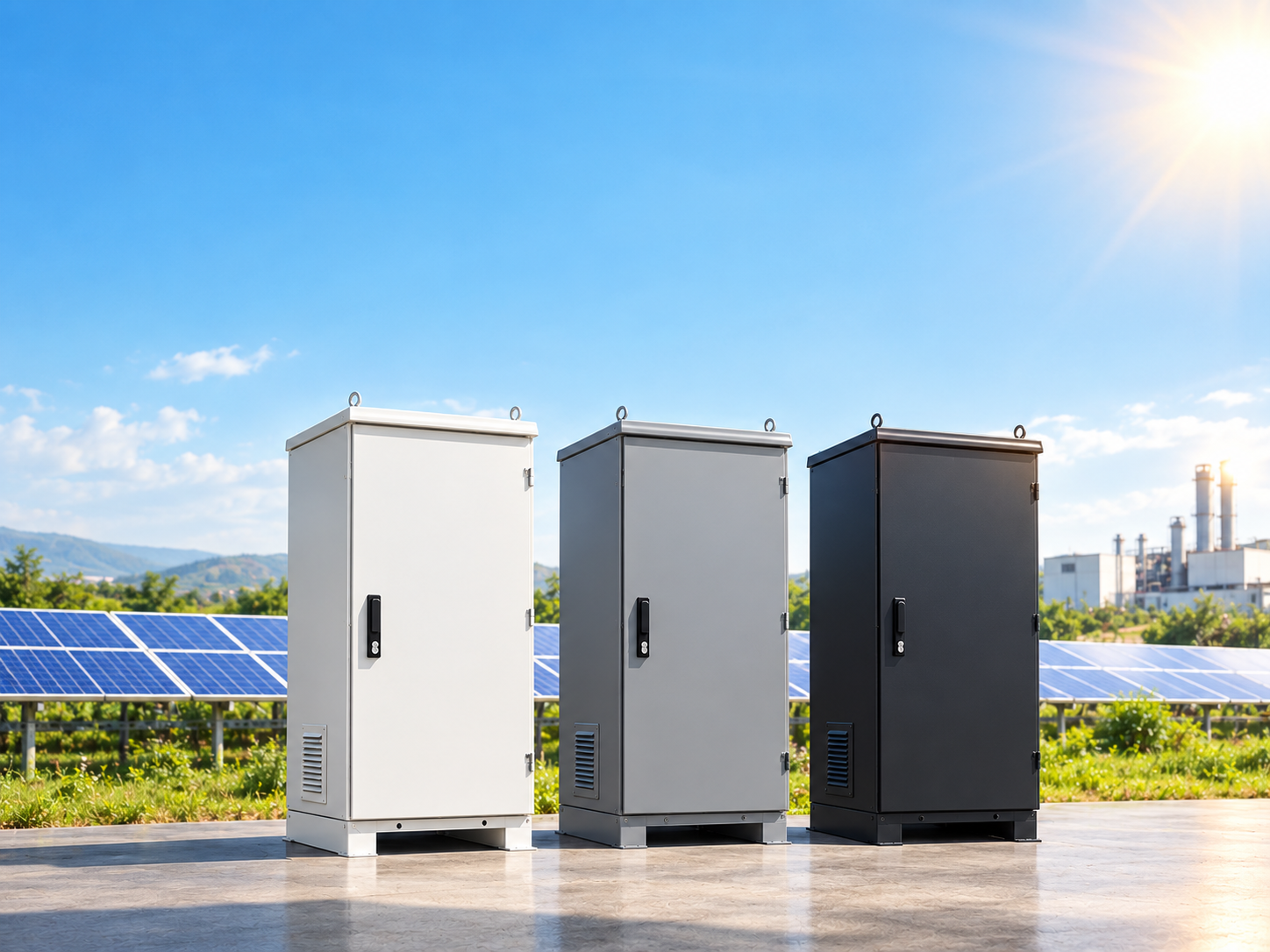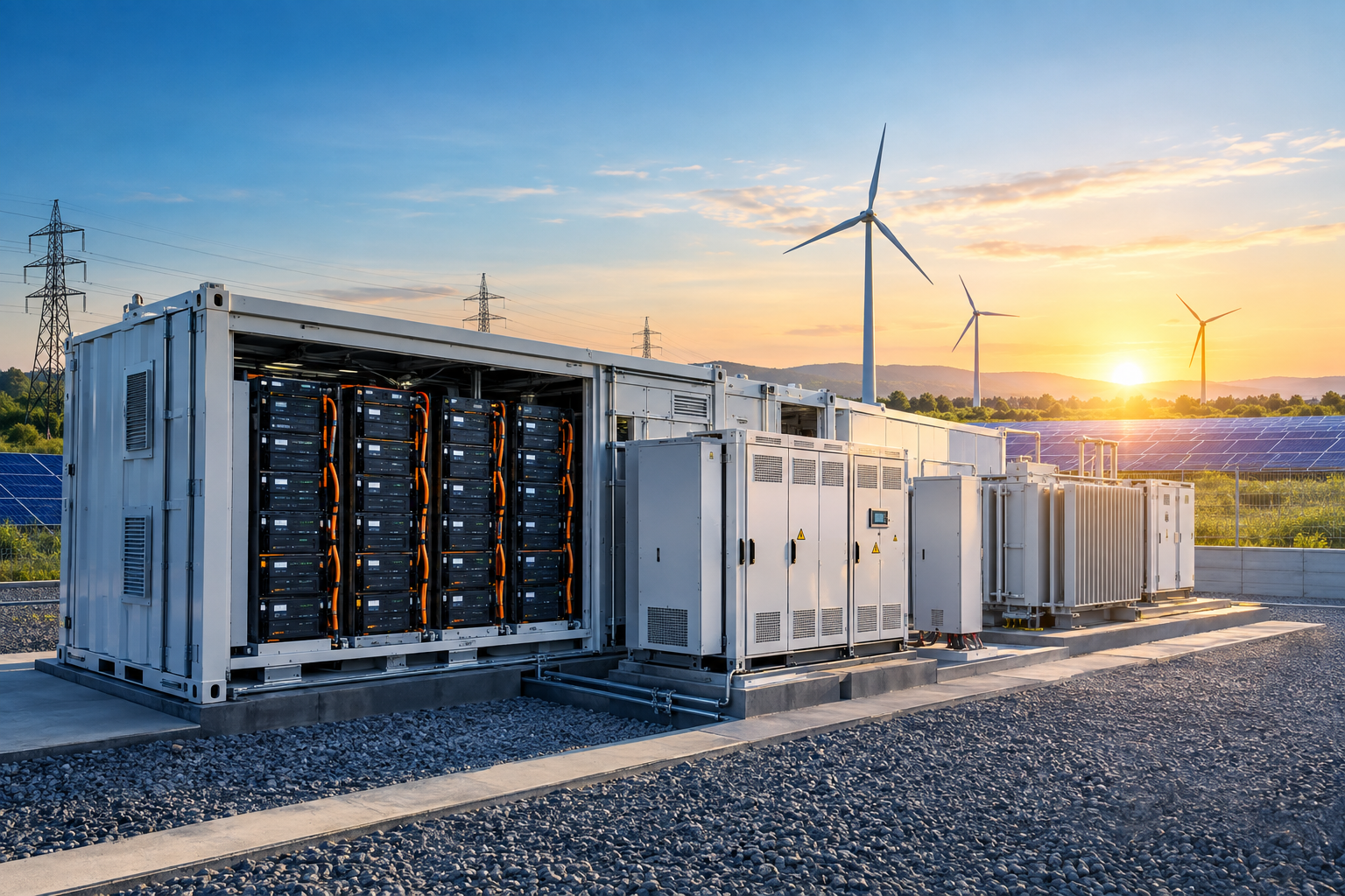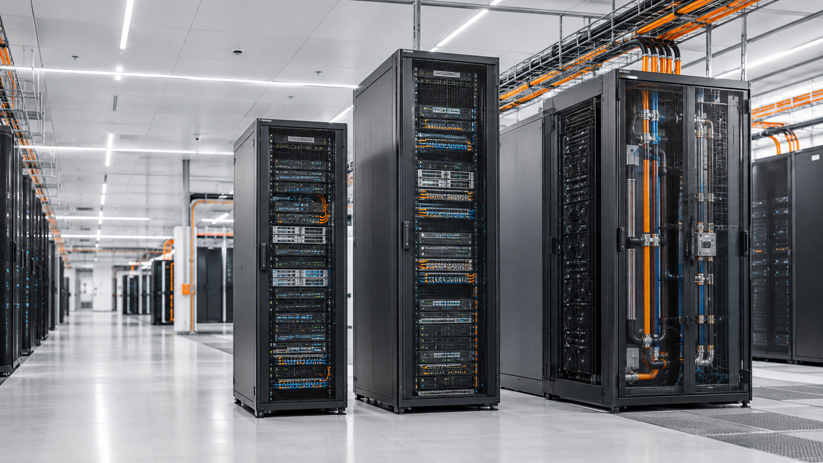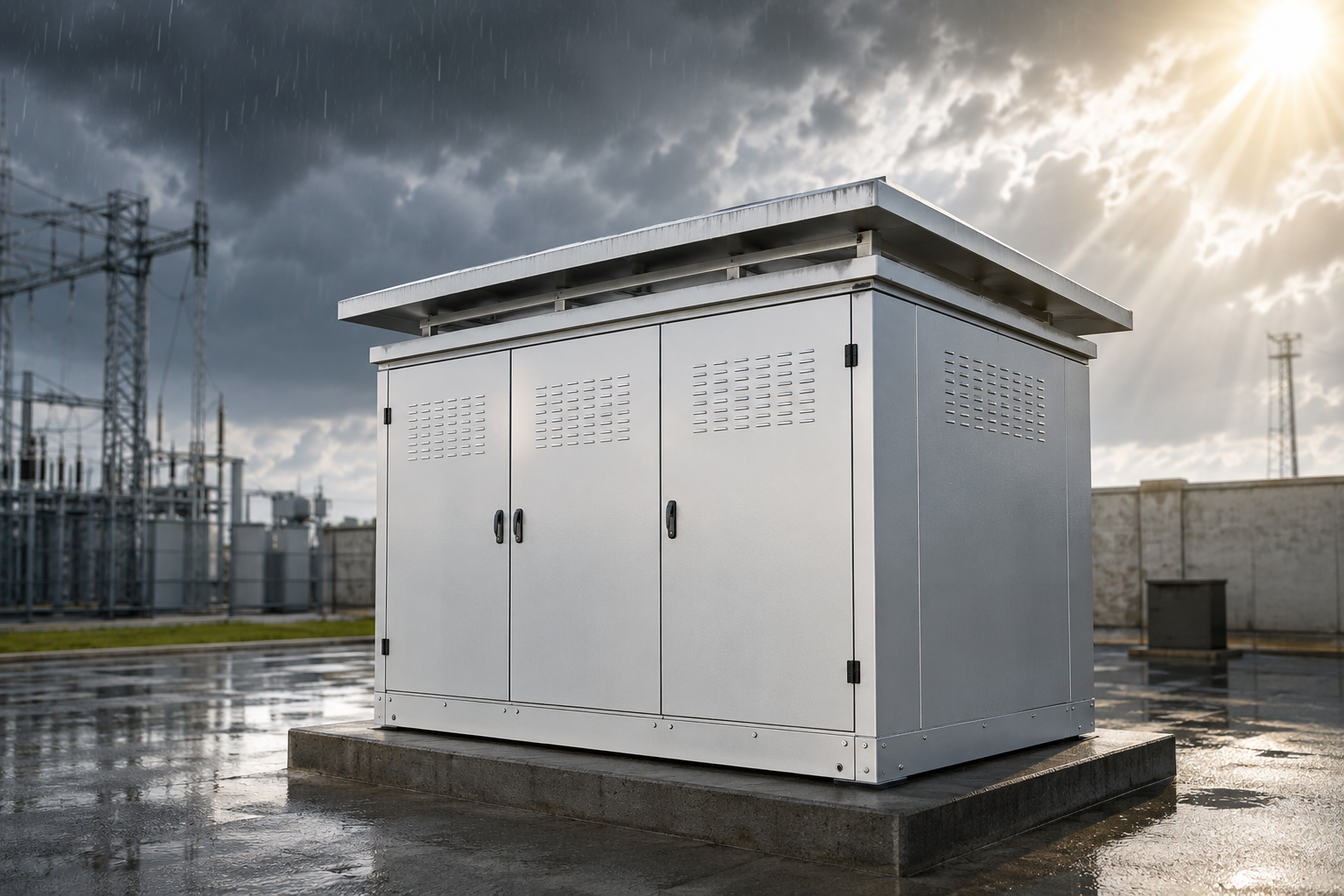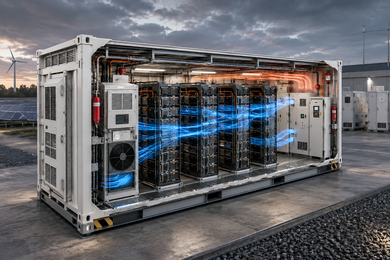
A Battery Energy Storage System (BESS) container may look simple from the outside: a steel enclosure filled with battery racks, cooling equipment, electrical systems and safety devices.
But inside, every centimetre matters.
The position of a battery rack, the direction of airflow, the location of the HVAC unit, the routing of power cables, and even the placement of service access can influence thermal performance, electrical losses, maintenance time, safety and overall BESS reliability.
As energy storage systems move from hundreds of kilowatt-hours to multi-megawatt-hour installations, BESS container design is becoming an engineering discipline of its own.
Modern systems are increasingly designed around high energy density. For example, Fluence's Gridstack Pro 5000 is designed to deliver up to 5.6 MWh within a 20-foot enclosure, demonstrating how much energy can now be packed into a relatively compact footprint.
But higher energy density creates a fundamental engineering question:
How do you fit more energy into the same container without compromising reliability, cooling, accessibility and safety?
The answer starts with the layout.
A BESS container is not simply a battery cabinet placed inside a shipping container.
It is an integrated system containing multiple interacting subsystems:
Battery racks and modules
Battery Management System (BMS)
Power distribution equipment
HVAC or liquid cooling system
Fire detection and suppression systems
Gas detection and ventilation
Emergency shutdown systems
Auxiliary power systems
Communication and control equipment
Cable trays and power connections
Service and maintenance access
The challenge is that these systems have different requirements.
Batteries need controlled temperatures.
Electrical equipment needs appropriate clearances.
Cooling systems need unobstructed airflow or coolant circulation.
Technicians need safe access.
Fire and gas protection systems need effective coverage.
And the enclosure itself must withstand environmental and operational conditions.
Therefore, BESS container layout is a balancing exercise between energy density, thermal management, electrical performance, safety and maintainability.
Battery racks are generally the largest components inside a BESS container, so their arrangement determines much of the remaining layout.
A poorly planned rack configuration can create:
Uneven cooling
Difficult maintenance access
Cable congestion
Higher local temperatures
Poor visibility of equipment
Increased installation complexity
The objective is not simply to install the maximum number of racks.
It is to create a layout where each rack operates within its required thermal and electrical conditions while remaining accessible for inspection and maintenance.
For example, racks may be arranged in rows with defined service aisles. The exact spacing depends on the battery technology, enclosure design, applicable standards, fire-test results and manufacturer's installation requirements.
This is increasingly important because modern fire-safety assessment looks beyond individual battery cells.
UL 9540A evaluates thermal runaway and fire propagation behavior and provides data that can support installation decisions such as separation between BESS units and fire/explosion protection requirements.
In other words, rack placement can become part of the safety engineering—not merely mechanical design.
Temperature is one of the most important variables affecting lithium-ion battery performance and life.
A BESS container can have thousands of battery cells operating within a relatively confined space. During charging and discharging, these cells generate heat.
If that heat is not removed effectively, temperature gradients can develop.
One section of the container may remain relatively cool while another experiences higher temperatures.
That can affect:
Battery efficiency
Cell aging
Available capacity
Charging/discharging performance
Battery life
Thermal safety margins
This is why HVAC placement and airflow design are critical parts of BESS engineering.
A cooling system positioned without considering rack arrangement can create short-circuit airflow paths, where cooled air reaches nearby equipment while more distant racks receive insufficient cooling.
The result?
The HVAC may appear to be operating correctly, while some battery racks still run hotter than intended.
Modern BESS designs are therefore increasingly using liquid cooling, particularly where high energy density is required. Some commercial containerized systems use liquid-cooled battery packs specifically to improve temperature control and reduce auxiliary energy consumption.
The engineering principle is simple:
Cooling capacity is only useful when the cooling reaches the equipment that needs it.
When engineers discuss BESS cooling, it is easy to focus only on the HVAC unit.
But HVAC capacity alone does not guarantee effective cooling.
The entire internal geometry matters.
Consider two identical 3 MWh BESS containers.
Container A has:
Correct rack spacing
Balanced airflow paths
Proper return-air routing
Strategically positioned cooling equipment
Container B has:
Tightly packed racks
Obstructed airflow
Poor return-air circulation
Cooling equipment positioned without considering the rack configuration
Both may have the same HVAC capacity.
Yet their thermal performance can be very different.
This is why airflow modelling and thermal analysis can be valuable during BESS container design.
The same principle applies to liquid-cooled systems: coolant piping, manifolds, connections and service clearances need to be considered alongside battery rack positioning.
Another major consideration is the routing of DC and auxiliary electrical connections.
Battery racks need to connect to the appropriate electrical distribution and power conversion equipment.
A well-engineered layout aims to control:
Cable lengths
Voltage drop
Cable routing complexity
Electromagnetic considerations
Heat accumulation
Accessibility
Installation time
Shorter cable routes can reduce material and electrical losses, but the shortest possible route isn't necessarily the best route.
Cable trays should not interfere with ventilation, maintenance access or safety systems.
Power cables should also be separated and routed appropriately from communication and control wiring.
The layout therefore becomes a three-dimensional engineering problem:
Where equipment sits determines how electricity, cooling, communication and maintenance pathways move through the container.
The Battery Management System is one of the most important control layers in a BESS.
It monitors parameters such as:
Cell voltage
Module voltage
Temperature
State of charge
State of health
Battery faults
Charging and discharging conditions
BMS architecture can operate across different levels, from cell and module monitoring through rack-level and system-level controls.
Because the BMS interacts closely with battery racks, its physical placement and communication architecture should be considered during the initial layout.
Communication cables should be routed carefully and protected from unnecessary interference or physical damage.
At the same time, service personnel should be able to access relevant control equipment without having to dismantle unrelated systems.
This is a classic example of why electrical design and mechanical enclosure design cannot be treated as separate activities in BESS manufacturing.
One of the most important developments in modern BESS engineering is the increasing focus on what happens during abnormal events.
Lithium-ion batteries can experience thermal runaway. If propagation occurs, heat and gases can affect surrounding equipment and potentially neighboring BESS units.
This makes internal containment, detection, ventilation, fire protection and external spacing interconnected design considerations.
UL 9540A is specifically designed to evaluate thermal runaway, fire and explosion characteristics of battery energy storage systems. Its 2026 edition introduced an updated installation-level large-scale fire test approach.
The important takeaway for container designers is:
The final layout should not be designed first and tested later as an afterthought.
The battery arrangement, enclosure configuration, ventilation strategy and safety systems need to be engineered as a complete system.
For example, Fluence reported large-scale testing of its Gridstack Pro 5000 using four enclosures at minimum spacing. The company stated that the testing demonstrated no enclosure-to-enclosure propagation under the tested conditions.
This illustrates an important industry shift: BESS safety is increasingly being demonstrated at the system and installation level, not just at the individual battery-cell level.
A container may perform perfectly during normal operation but become difficult to maintain if equipment is packed too tightly.
Imagine a battery module that needs replacement.
If technicians cannot easily reach the module, they may need to remove adjacent equipment or disconnect additional systems.
That increases:
Maintenance time
Downtime
Labour requirements
Safety exposure
Risk of installation errors
Good BESS layout therefore includes defined service paths, removable panels, accessible electrical connections and practical lifting/replacement strategies.
This becomes particularly important for utility-scale BESS projects, where the cost of downtime can extend beyond the replacement component itself.
Designing for maintenance is designing for uptime.
A useful example of the industry's move toward higher-density BESS is Fluence's Gridstack Pro 5000.
The system is designed for up to 5.6 MWh in a 20-foot enclosure and has undergone large-scale fire testing involving multiple enclosures at tight spacing. Fluence reported that the tested configuration prevented fire propagation to neighboring enclosures under the test conditions.
The significance is bigger than the product itself.
As BESS systems move toward higher MWh capacity per container, engineers have to solve several problems simultaneously:
More batteries → more energy density → more heat → tighter engineering constraints → greater importance of thermal management, safety and layout.
Other major BESS players such as Tesla and Wärtsilä have also deployed large-scale containerized energy storage architectures, showing how the industry is moving toward highly integrated, factory-engineered systems.
The engineering lesson is clear:
A BESS container is no longer just an enclosure for batteries. It is a compact energy infrastructure system.
The best BESS container layouts are developed by considering the complete system from the beginning.
A typical design workflow can include:
Determine cell chemistry, module configuration, rack dimensions, voltage levels and target MWh capacity.
Optimise rack quantity, spacing, service access and electrical connections.
Select HVAC or liquid cooling and establish the required airflow or coolant paths.
Route DC power, auxiliary power, grounding and communication systems.
Position detection, emergency shutdown, fire protection, ventilation and relevant pressure-relief provisions according to the applicable design and test requirements.
Check whether technicians can safely access components that require inspection, replacement or servicing.
Use electrical calculations, thermal analysis, airflow modelling, structural checks and applicable certification/testing to validate the final configuration.
This approach avoids a common mistake:
designing the container around available space instead of designing the space around system performance.
BESS capacity is often communicated in simple numbers:
1 MWh. 3 MWh. 5 MWh. 10 MWh.
But behind every number is a highly engineered physical system.
The internal layout determines how batteries receive cooling, how power travels, how technicians access equipment, how safety systems respond and how the container behaves under abnormal conditions.
As energy density increases, BESS manufacturers cannot simply keep adding battery racks.
They need to engineer the entire container around thermal performance, electrical efficiency, safety, accessibility and long-term reliability.
That is why BESS container design is becoming an increasingly important part of energy storage engineering.
The battery may store the energy—but the container layout determines how reliably that energy can be delivered.
A BESS container is an engineered enclosure that integrates battery racks with battery management, cooling, electrical distribution, safety and control systems for stationary energy storage.
Layout affects thermal management, electrical performance, maintenance access, equipment reliability and safety.
Typical equipment includes battery racks, BMS, cooling systems, electrical distribution, fire detection/protection, ventilation, auxiliary power and communication systems.
Effective cooling keeps battery cells within their required operating temperature range, helping maintain performance, efficiency and battery life.
UL 9540A is a test method used to evaluate thermal runaway, fire and explosion behavior of battery energy storage systems and can provide data supporting installation and safety decisions.