Introduction
India has multiple high-risk seismic regions including Zones III, IV, and V.
Battery Energy Storage Systems (BESS), telecom backup systems, EV infrastructure, and industrial UPS rooms increasingly deploy high-density battery racks.
Structural failure of battery racks during earthquakes can lead to:
Electrical short circuits
Thermal runaway propagation
Fire hazards
Operational shutdown of critical infrastructure
Mechanical stiffness is therefore a primary design requirement, not a secondary structural parameter.
What Is Mechanical Stiffness in Battery Racks
Mechanical stiffness is the resistance of a structure to deformation under applied load.
In battery racks, stiffness determines:
Lateral sway under seismic excitation
Resistance to buckling
Deflection limits under static and dynamic forces
Integrity of bolted joints and anchor systems
High stiffness reduces:
Module displacement
Connector stress
Risk of cascading cell failure
Why Seismic Zones Demand Special Design
Static gravity loads act vertically and remain constant.
Earthquake forces are:
Horizontal and vertical
Cyclic and reversible
Rapidly changing
Earthquake loading introduces:
Inertial forces proportional to mass
Amplification due to resonance
Uplift forces at anchor points
Non-structural components such as battery racks often fail before the main building structure.
Static Load vs Dynamic Seismic Load
|
Parameter |
Static Load |
Dynamic Seismic Load |
|
Force Type |
Constant gravity load |
Time-varying inertial force |
|
Direction |
Vertical |
Multi-directional |
|
Design Basis |
Weight of batteries |
Ground acceleration spectrum |
|
Governing Factor |
Material strength |
Stiffness, damping, frequency |
|
Failure Mode |
Buckling, yielding |
Overturning, fatigue, resonance |
|
Safety Margin |
Moderate |
Higher due to unpredictability |
Anchor Loading in Seismic Conditions
Anchors transfer seismic forces from rack to foundation.
Inadequate anchoring leads to:
Sliding
Overturning
Baseplate tearing
Concrete pull-out failure
Key Anchor Design Considerations
Shear and tensile capacity must exceed calculated seismic forces.
Embedment depth must prevent pull-out under uplift conditions.
Anchor spacing must avoid group interaction failure.
Multi-directional loading must be considered.
Baseplates must distribute load evenly.
Failure Modes to Consider
Concrete breakout
Steel anchor yielding
Edge failure near slab boundaries
Fatigue cracking in cyclic loading
Center of Gravity (CG) Shift During Thermal Runaway
Thermal runaway can cause:
Cell swelling
Gas venting
Uneven mass distribution
Structural distortion
These phenomena alter the center of gravity.
Why CG Shift Is Dangerous in Seismic Zones
Increased top-heaviness increases overturning moment.
Dynamic response characteristics change.
Amplified displacement under lateral acceleration.
Anchor uplift forces increase significantly.
Mitigation Strategies
Keep heavier battery modules at lower tiers.
Use modular rack segmentation to limit mass redistribution.
Provide diagonal bracing for torsional stiffness.
Design for worst-case CG shift scenarios.
Dynamic Performance Parameters
Natural frequency
Must not match dominant seismic frequency range.
Resonance dramatically increases displacement.
Damping ratio
Higher damping reduces amplitude.
Steel racks typically have low inherent damping.
Stiffness-to-mass ratio
Higher stiffness reduces displacement.
Excessive stiffness increases force transfer to anchors.
Mode shapes
Tall racks exhibit higher mode amplification.
Multi-tier systems require modal analysis.
Relevant Indian Codes and Standards
IS 1893 (Part 1) – Earthquake Resistant Design Criteria
IS 4326 – Earthquake Resistant Construction
IEC 61439 – Low voltage switchgear structural compliance
IEEE 693 – Seismic qualification of electrical equipment
Compliance should include:
Seismic zone factor
Importance factor
Soil condition factor
Response reduction factor
Real-Life Indian Deployment Examples
Tata Power
Grid-scale BESS projects in western India.
Seismic-compliant anchoring systems in battery containers.
Reinforced base frames to manage lateral forces.
Dynamic load validation integrated into design stage.
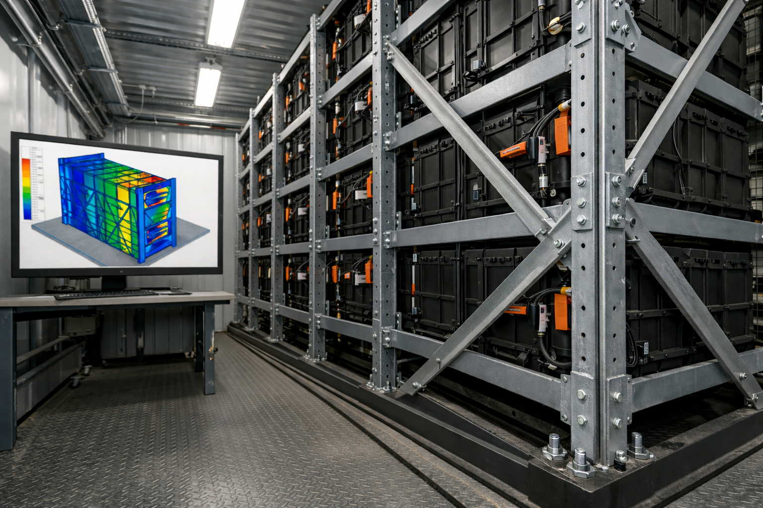
Larsen & Toubro
Industrial energy storage and infrastructure projects.
Use of structural bracing to improve stiffness.
CG optimization in rack design.
Application of finite element analysis before fabrication.
Adani Green Energy
Large renewable integration projects.
Shock-absorbing interfaces between rack and floor.
Cross-bracing systems for lateral rigidity.
Enhanced anchor embedment depth in seismic regions.
Reliance Jio
Telecom backup battery systems across multiple seismic zones.
Multi-anchor baseplates for redundancy.
Reinforced rack frames for communication uptime reliability.
Indian Railways
Battery racks in signaling and control centers.
Seismic-qualified non-structural equipment installation.
Heavy-duty anchoring to prevent tipping in control rooms.
Engineering Best Practices
Conduct site-specific seismic hazard assessment.
Perform response spectrum analysis.
Validate stiffness using finite element modeling.
Increase anchor redundancy for mission-critical sites.
Ensure uniform torque application in anchor bolts.
Design for uplift forces explicitly.
Consider worst-case thermal runaway load shift.
Schedule periodic anchor inspection and torque checks.
Common Design Mistakes
Designing only for static load capacity.
Ignoring multi-directional seismic forces.
Using generic commercial anchors without seismic certification.
Neglecting CG shift scenarios.
Underestimating overturning moments in tall racks.
Skipping dynamic simulation due to cost constraints.
Impact of Poor Seismic Design
Rack collapse
Battery module ejection
Electrical arcing
Fire propagation
Downtime in critical facilities
Insurance and compliance liabilities
How to Improve Mechanical Stiffness
Increase section modulus of vertical members.
Add cross-bracing in X or K configuration.
Use thicker baseplates.
Increase weld quality and joint rigidity.
Reduce rack height-to-width ratio.
Distribute mass evenly across tiers.
Strategic Importance for Infrastructure Projects
Data centers
Renewable energy plants
EV charging hubs
Telecom towers
Industrial plants
Hospitals
Seismic stiffness directly affects:
Operational continuity
Fire safety
Regulatory compliance
Long-term asset durability
Conclusion
Mechanical stiffness is central to seismic battery rack design.
Anchor loading determines structural survival during earthquakes.
CG shift during thermal runaway must be considered in design modeling.
Dynamic load behavior differs fundamentally from static load rating.
Indian infrastructure leaders are already incorporating seismic stiffness into energy storage deployment.
Proper seismic engineering reduces risk, downtime, and catastrophic failure.
Frequently Asked Questions
1. Why is static load rating not sufficient in seismic zones?
Static rating considers only gravity. Seismic design must account for horizontal inertia forces and dynamic amplification.
2. What causes anchor failure during earthquakes?
Excess uplift force, shear overload, inadequate embedment depth, or concrete breakout.
3. How does thermal runaway affect rack stability?
It alters mass distribution, shifts center of gravity, and increases overturning risk.
4. What analysis method is preferred for seismic rack design?
Response spectrum analysis or time-history simulation.
5. Can existing racks be retrofitted for seismic compliance?
Yes, through additional bracing, upgraded anchors, thicker baseplates, and structural reinforcement.